

Capacitance Meter
An auto-ranging capacitance meter.
Timeline
September 2024 – November 2024
Implementation Details
Tools: Teensy Microcontroller, Altium, and LTspice.
Teammate: Donald P.
Specifications
- Wall powered, 5V DC only.
- Auto ranges between 20 pF and 200 µF.
- Resolution: the display has 7 total digits going from 0.0000 to 999.9999 in pF to µF, measurement is accurate within 3 and ½ digits.
- Accuracy: 3% from 2 nF to 2 µF, and 10% from 20 pF to 2 nF and 2 µF to 200 µF.
- Update with a button press.
- Does not require any laptop or other computer to operate, just requires a power source.
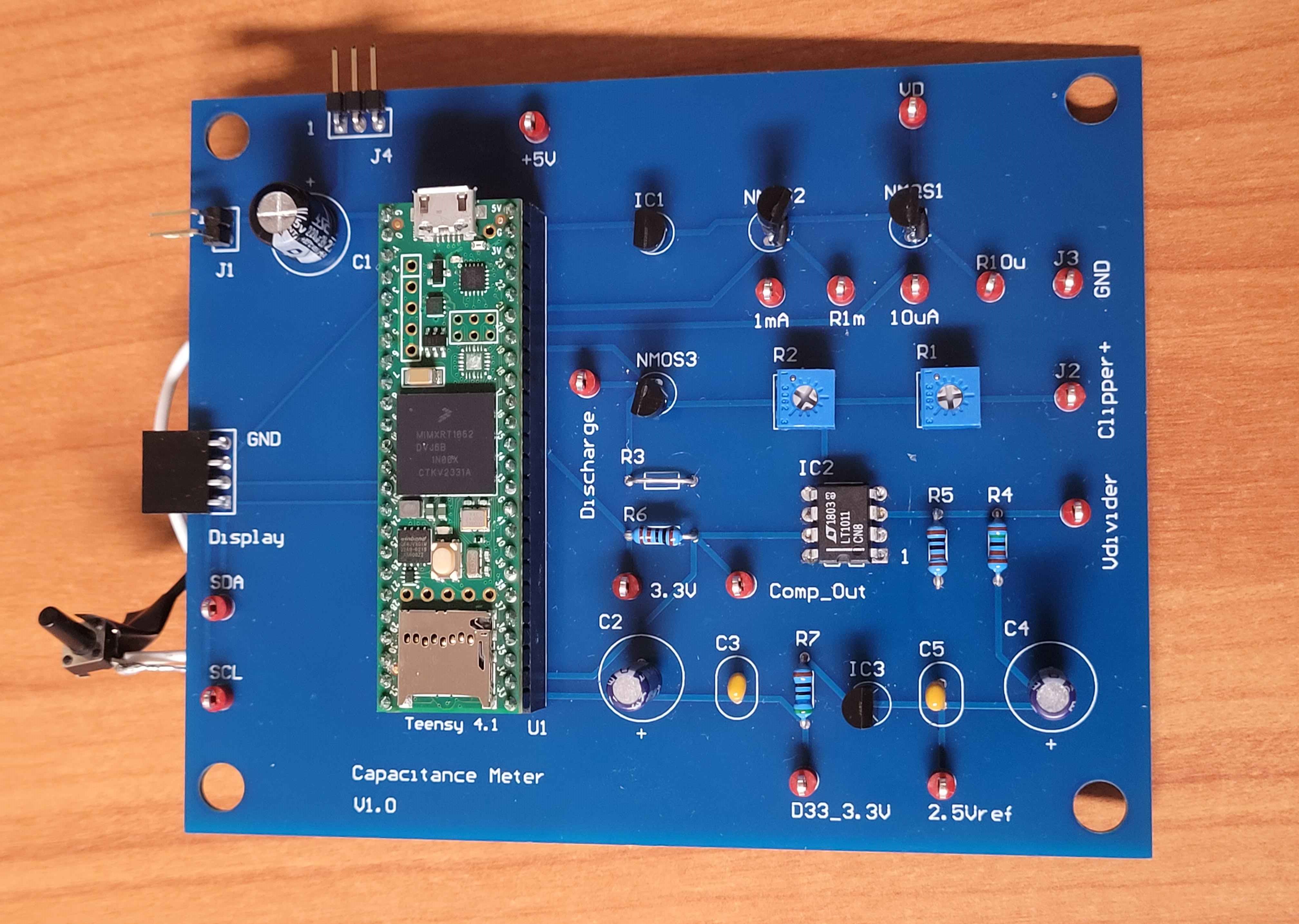
- Utilizes clip lead to clip lead adapters to connect to capacitors and 2 test points located on the board labeled Clipper+ and GND for positive end and ground end respectively.
Source Code:
Link to the GitHub repository: Capacitance Meter Code
Planning
Tasks Checklist:
- Project timeline planning
- Preliminary method research
- Initial schematic design
- Design review 1
- Schematic design with feedback integration
- PCB design
- Design review 2
- Feedback integration
- Testing components
- Breadboard prototype
- PCB ordering
- Software design
- PCB assembly
- Measurement testing
- Measurement calibration
- design
- Documentation and report
Design
Theory of Operation:
To measurement capacitance, we use the constant current source method, deriving from the capacitor equation.
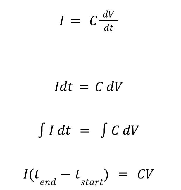
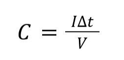
In this equation, we hold the current constant and charge the capacitor to a certain threshold, which is 1 V in our design, the calculated capacitance after rearranging the equation above is as follows:
Software Flowchart:
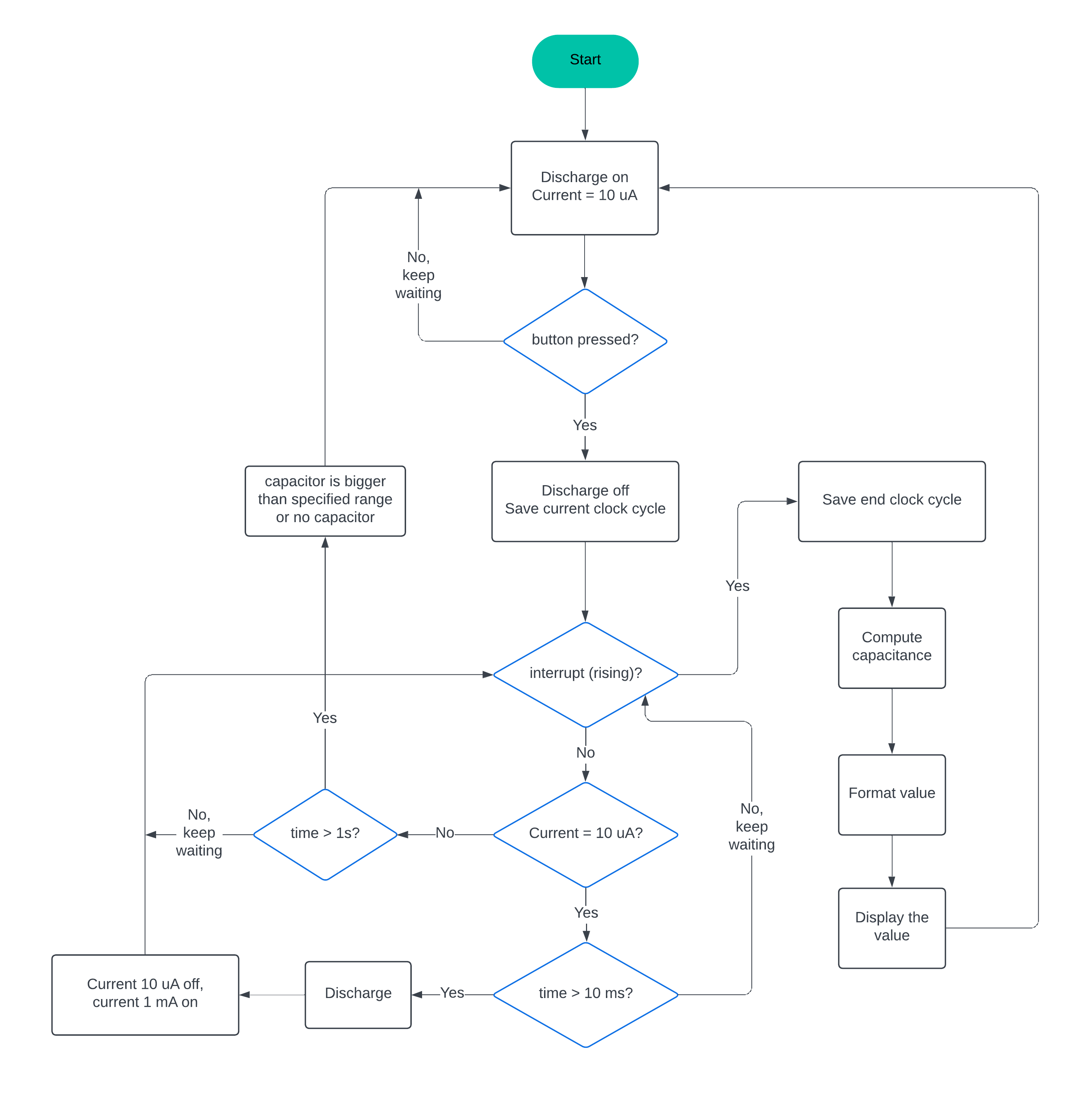
Software Flowchart
PCB:
The PCB has 2 layers:
- Signal (top layer)
- Ground
Below is a picture of each layer:
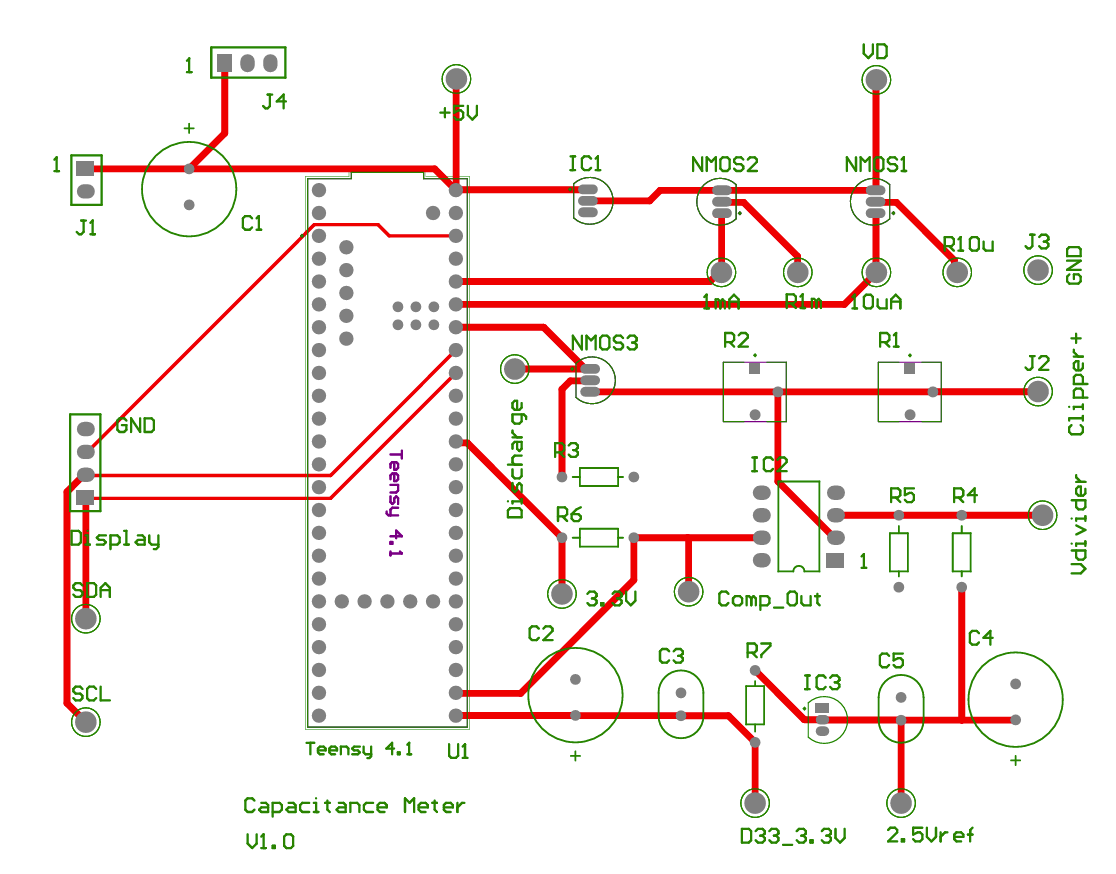
Top Layer
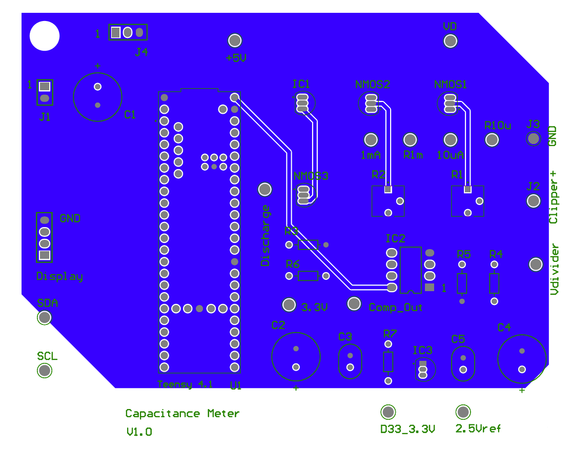
Bottom Layer
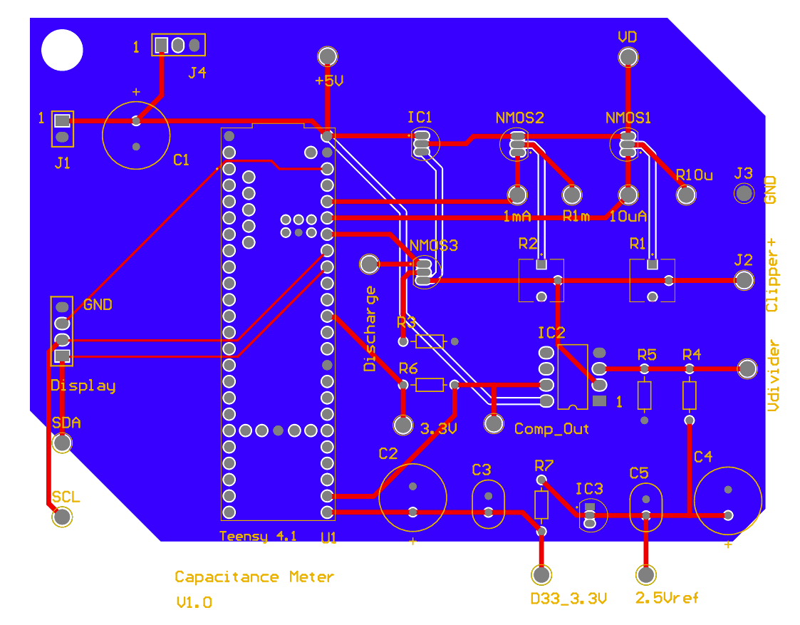
Top and Bottom Layer
Outcomes:
Below are the pictures of the finished prototype breadboard, PCB, and case.
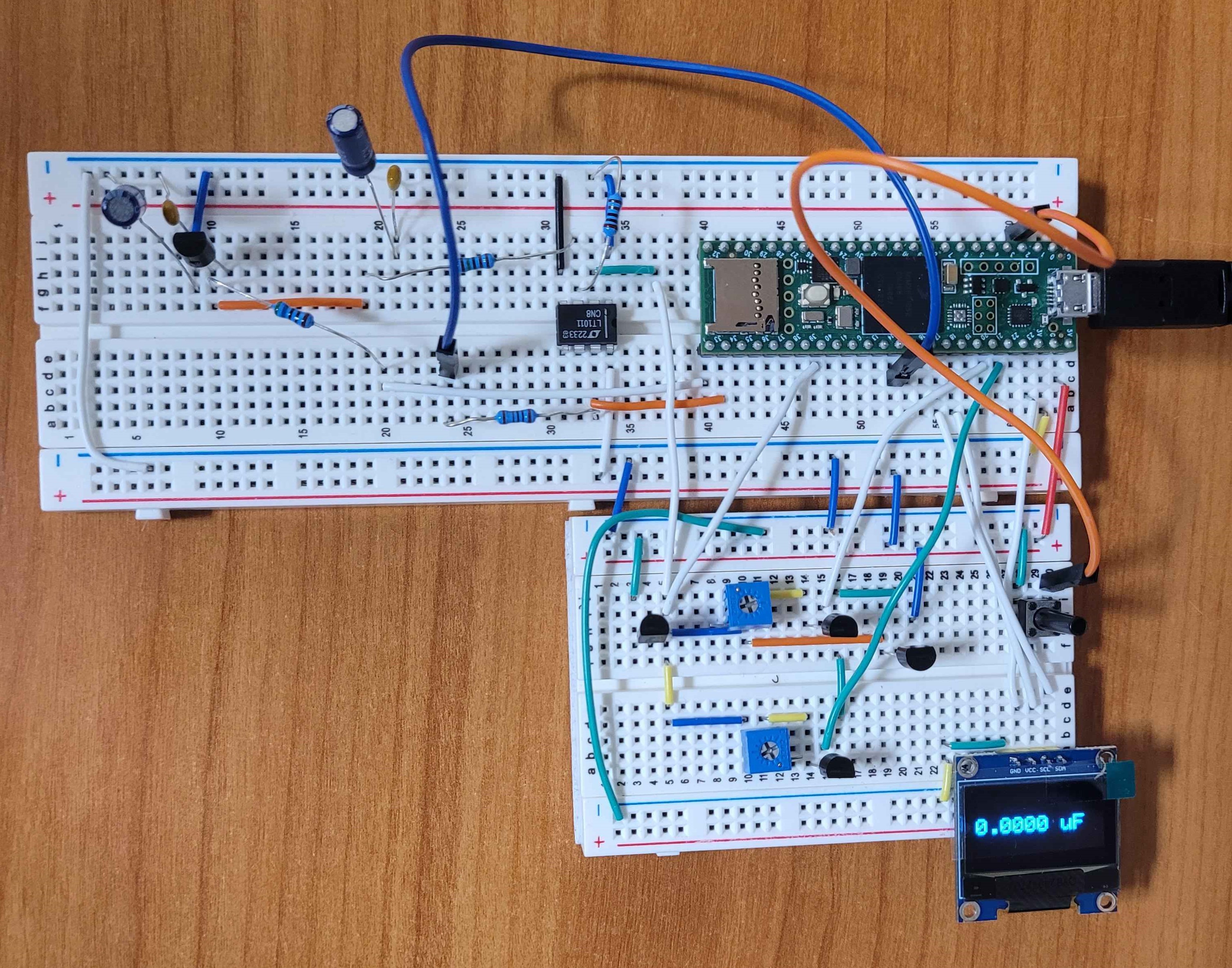
Breadboard Prototype
Capacitance Meter PCB
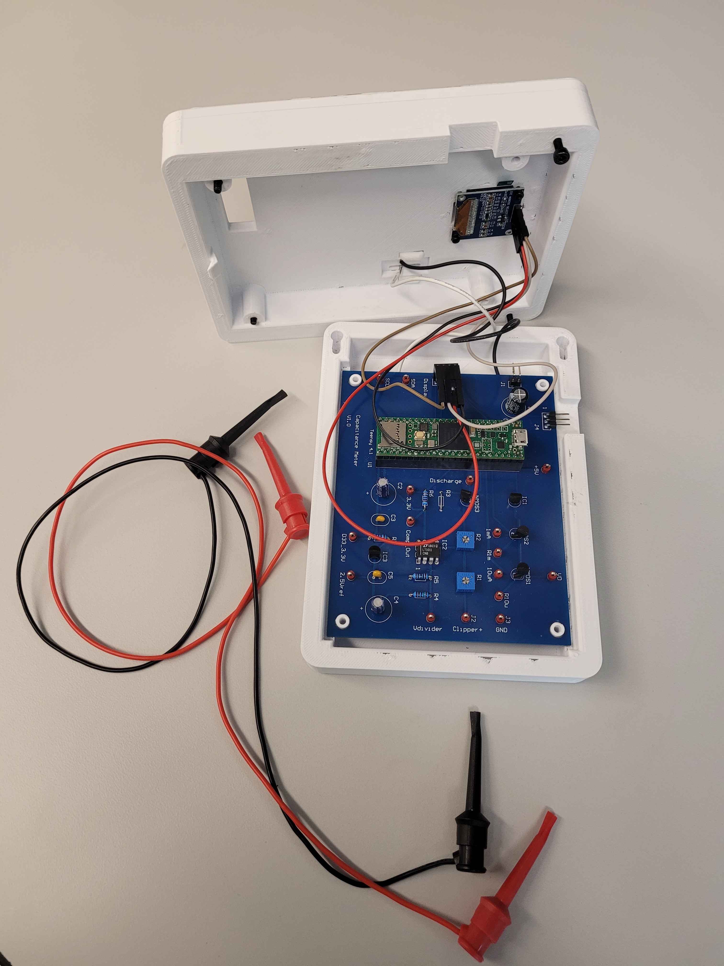
Capacitance Meter PCB with Case
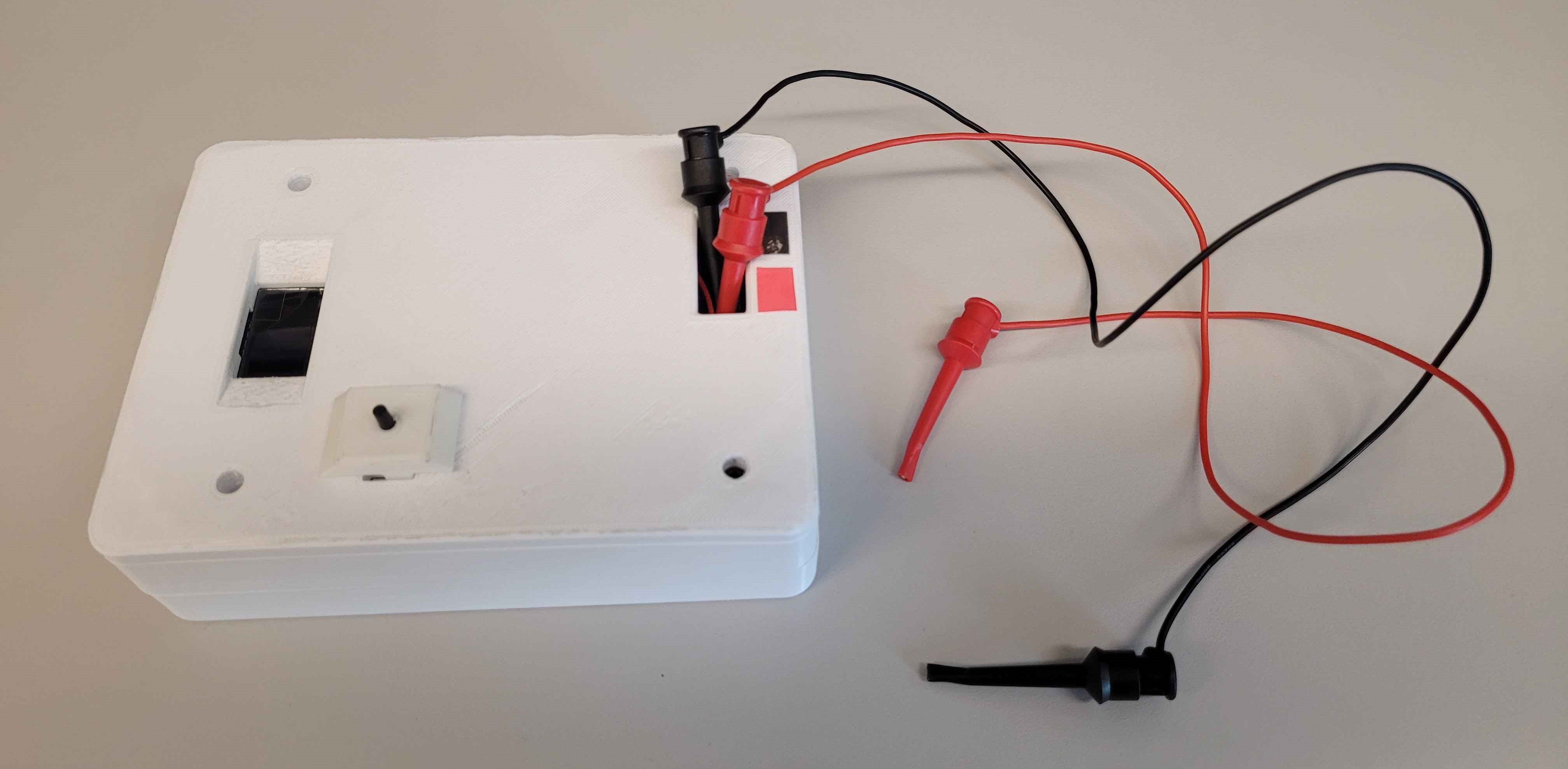
Capacitance Meter PCB in the Case